Oil
Liquid Refrigerant
Discharge / High Side
Electrical
Various Components
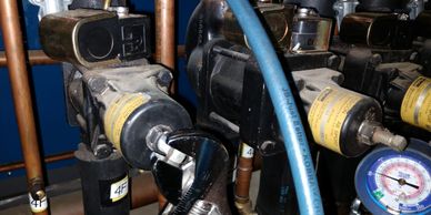
EPR
EPR= Evaporator Pressure Regulator valve. It is used to keep a constant pressure on the suction side. This keeps a consistent TEMPERATURE, because TEMPERATURE and PRESSURE GO TOGETHER.
How it Works
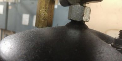
OCV
This is an OCV Valve. If the oil pressure in the oil reservoir gets excessive pressure in it, it will open up (SPRING LOADED), and relieve its pressure into the suction line header. Usually RACK systems have an OCV 20, which means 20 PSI differential.

Heat Reclaim Hot Water Tank
This is to pre-heat the store incoming hot water using the DISCHARGE from one of the RACKS. The discharge header comes from the compressors to this tank and out of the tank to the condenser. NOTE: It can be a source of a leak sometimes in a system and can be tough to detect.
How it Works

Hot Gas Defrost Valve
This valve is a 3-way in the CLOSED position. It allows suction pressure to come back to the suction header. When energized, it will CLOSE off the suction and allow hot gas to go to the cases in defrost mode. It has a slide valve inside of it like a heat pump does. NOTE: The small 1/4″ line is known as a “PUMP OUT LINE.”
How it Works

50% Condenser Lineset
The purpose of this setup is for LOW AMBIENT conditions, when the condenser is located outside, and temperatures can get generally below freezing (32 DEGREES). It is generally driven by a sensor.
How it Works

Discharge Holdback Valve
This valve helps to keep a constant head pressure on the condenser. This keeps constant liquid pressure to the liquid lines at the rack.
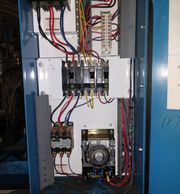
One On One System
This is a “ONE ON ONE” system generally used for a lineup or freezers. Notice the time clock inside of panel. NOTE: To check the time clock on a system that uses one, use a SHARPIE felt tip and mark where the pointer is just above the knob. Wait 15 minutes and if it doesn’t move, then the clock is bad. Sometimes the clock will hang up on the the defrost pin and stop. You will generally get a call of CASE WARM. If you do this is one item to check. If it is on defrost upon arrival, turn the knob past the defrost pin, mark it, and wait 15 minutes. More than likely the gears are stripped out on the motor, which will also dictate that you replace the time clock. When changing the clock, shut the MAIN breaker off inside the panel, and change ONE wire at a time. Before removing wires from terminals, verify there is no voltage using your volt meter. NOTE: 4 Terminal on the time clock is ALWAYS the control circuit, be it for the T-Stat, Contactor are some examples. 3 Terminal is generally for the DEFROST HEATERS.

Liquid Hand Valve
This is a liquid hand valve and is generally located inside the case itself. On rare occasions you will see them inside motor rooms, on the individual liquid line circuit.
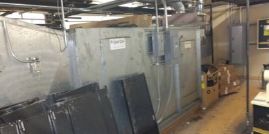
AHU
Air Handler Unit handles both A/C and Heating. This is where some of the discharge lines will go for AIR heat reclaim (STORE HEATING), and has a belt driven fan (Squirrel Cage fan).
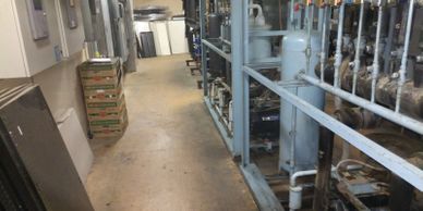
Rack
This is what is known as a RACK, based on how its design encompassing All the major components ..Compressors, EPRs, Liquid line solenoids, reciever , Electrical associated with the aforesaid mentioned items, and othe various controls, (LPC, HPC,OFC).
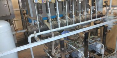
Rack 2
Refrigeration compressors of differing horse powers piped together are also known as an UNEVEN PARALLEL RACK, due to various HP compressors. You can have a 7.5, 10, and 15HP, hence they are uneven in horse power.
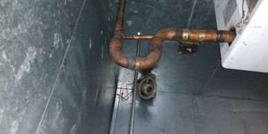
P-Trap
Always used when the compressor/compressors are located ABOVE the coils. This aids in getting oil back upstairs to the compressors. NOTE: Notice how the line comes out of the evap coil and there narrows down on the riser. This is very common to do for R22 systems. R22 DOES NOT carry oil well at all, so the VELOCITY has to be sped up to get the oil to return.
Evaporator Pressure Regulator
How it Works
EPR = Evaporator Pressure regulator. The EPR helps keep a constant pressure on the evaporators, thus keeping a constant temperature. It is used in ALL applications, LOW and MEDIUM temp racks. If you have a whole lineup down, check this item out. Sometimes the solenoid will fail, causing high temp issues. If a lineup of multi deck meat is frozen, the valve could be bleeding by. To check this put your gauges on and put system into defrost and the pressure should RAISE. If it does then it is good. If the pressure does not change or stays at rack pressure in defrost, then it is bleeding by. When the solenoid fails, the valve will fail to CLOSED position. Sometimes if a lineup is running too cold or too warm, then you can adjust the pressure from here. Use your gauges and T&P chart to convert pressure to temperature. In rare instances the valve will get stuck in a position where the cases run too cold or warm. At this time it will need to be rebuilt. Sporlan and Parker are the two most common EPR’s used in grocery store refrigeration. EPR’s are NOT ALWAYS located at the rack. They can be inside the case, under the case, or on top of the case. Usually under the EPR body is a cap. When you take the cap off, there will be a SMALL SLOT to put a flat bladed screwdriver in and open it up. It puts the EPR in manual mode to get some refrigeration going, utnil you replace the solenoid coil. It buys you some time to make the next move on the service call. Another reason that you may not be able to get an EPR to adjust, is if the coils (EVAPORATORS) are frozen in ice. The pressure will be LOW, more than likely due to not being able to pick up heat from the product. If you encounter this situation, go to the case/cases in question and check the airflow. If there is none, then you will need to de-ice the coil/coils with a hose and hot water.
Heat Reclaim
How it Works
HEAT RECLAIM is a basic operation. The discharge line is routed from either the LOW or MEDIUM temp rack to either a hot water tank or to the AHU (AIR HANDLER UNIT). For the hot water tank the discharge, gas pre-heats the store hot water saving energy on gas or electric. Next it routes through the tank then out of the tank to the condenser, to be condensed back to a liquid, or the discharge line can be routed to the AHU for store heat. All that is being done is moving heat around in a vicious cycle. There will be a THREE WAY valve to route to heat reclaim units, or straight to the condenser. A few things to know is that if your receiver is low on refrigerant you can shut the heat reclaim off to keep the liquid strictly within the confines of the refrigeration system. They use a lot of gas, especially the AHU. When leak checking the store, it is very important to check both these systems, as they have been known to be a big source of leaks.
Hot Gas Defrost
How it Works
Instead of using an electric heater, some refrigeration systems use HOT GAS. Generally there is a line ABOVE the EPR from the discharge header. The EPR solenoid will DE-ENERGIZE, and simultaneously ENERGIZE the solenoid on the HOT GAS line, and send it through the suction in reverse flow of the normal suction travel. It will go through the evaporator, out a separate liquid line attached near the TXV, and back thru the liquid line at the main liquid header at the rack. The reason it does this is because the hot gas will condense to a liquid, so it makes sense to send it to the liquid header. Now at the rack there will be what is called a LIQUID HOLD BACK VALVE. It creates a differential between the liquid in and out of it of approx 25 PSI. It is basically a TRAFFIC COP for liquid so the condensed liquid coming back from hot gas defrost can merge with the main liquid line. This liquid will be at a HIGHER pressure than the liquid going to the cases on the sales floor. Sometimes what will happen is this valve will stick, NOT allowing a differential,or if the piston is stuck it can cause a differential even when a system is not in defrost . The best way to know what is going on is to hook up your gauges to see if there is a differential, or check the solenoid for power. If there is power, then the coil is bad. If it is working (SOLENOID), then the valve will either have to be replaced or rebuilt. Most of the time it is replaced. this is only if you DO NOT measure a differential on the valve.
Split Condenser
How it Works
A split condenser is just what the name implies. When low ambient conditions are present (COLD/FREEZING) outside, where the condenser is most likely located, there will be a discharge line that will “T” off near the condenser, and will have valve on it. It will CLOSE using only half the condenser, but the same volume, to keep the head pressure up preventing liquid from “STACKING” or hanging out in the condenser. Liquid refrigerant will want to stay in the COLDEST place possible which is the CONDENSER. This will enable the whole system to keep the liquid moving from the condenser, to the receiver, and finally out to the cases. When it is REALLY hot outside, or high ambient conditions, that same valve will OPEN, having more condensing area and to keep the head pressure from getting TOO high. Basically it is more surface area to condense, lowering the condensing pressure/temperature. These valves like any other are prone to failure. Sometimes it will stick or the solenoid will go bad. This can be determined by using your gauges on it as well. NOTE: Air cooled condensers have what are called FAN CYCLING switches. They stage fans on based on PRESSURE/TEMPERATURE. Some will do the same thing but based on TEMPERATURE of drop leg. These are also items to check when having problems with high discharge pressures. The switches that are PRESSURE activated can also be a source of refrigerant leaks, so ALWAYS check the pressure switches as well.
Additional Components

Discharge Muffler
A discharge muffler is used to smooth out the pulsations of the compressor, much like a muffler on a car, with the pistons moving up and down. Without it your gauge needle would bounce back and forth.
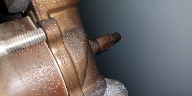
Manual Stem EPR
Notice the stem on the back of this EPR. To manually operate it, remove the cap, and turn in the stem. You can do this in a pinch to get some refrigeration going for the circuit this serves, but only TEMPORARILY. NOTE: When you have fixed the issue associated with the EPR, DO NOT forget to run the stem back OUT. Remember Stem OUT for auto operation and stem IN for MANUAL operation.

Oil Level Controller
Notice the flare nut on top of the oil level controller. Behind the flare nut is a little mesh screen that can get plugged with debris. To clean the screen, shut off the line going to it, loosen the flare nut, remove the screen, spray it with electrical contact cleaner, put the screen back in, tighten the flare nut, and open valve back up.

Manual Stem LLS
This is a Liquid line solenoid. Notice how it has a manual stem like the EPR. If needed you can turn in the stem for manual operation in an emergency. When you are done, make sure to turn the stem back OUT. NOTE: If you have a case/box coil flooding, or iced up, it is a good idea to check and make sure the stem is OUT. There have been numerous times when somebody forgets to do so, and left the stem turned in. Same thing applies on an EPR.
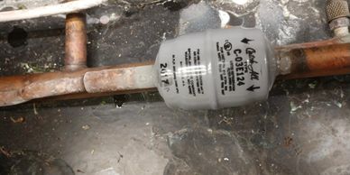
Filter Drier (Case)
Notice how this drier is frosted up on the OUTLET side. This is a classic example of a plugged drier. This is usually associated with a service call of “case running warm”. In this case you will have to pump down the case to 0 PSI, cut this drier out, weld in a straight piece of copper pipe, braze it, use a vacuum pump to get the air out of the system, and then start it back up. Sometimes it is helpful to put on the vacuum pump ahead of time. Once the system is at 0 PSI, this helps to get any and all residual refrigerant vapor from the lines, and makes it easier to braze without getting phosgene gassed. NOTE: If there is NO schrader/gauge port on the liquid line, PUT ONE IN to make the job easier for the next service tech. You can also use the suction schrader/gauge port. The system is intertwined, meaning it is a closed loop. The vacuum pump will remove the air from the suction and liquid side because they are still connected together.

Receiver Gauge
This is a receiver with a level indicator. These do go bad so do not rely on these as a sole means of checking receiver level. If you truly want to know what the level of liquid is you can do what is known as “TORCHING THE RECEIVER”. This is where you use your small canister hand held mapp gas torch, and run it UP & DOWN the receiver starting from the bottom and working upwards for a few minutes. Then with the BACK of your hand run it along the area you just “TORCHED” and it will feel WARM. That means there is liquid present up until when you feel a section that is HOT. Mark it with a sharpie to know where you’re at regarding the liquid level.

EEPR
This is an Electronic evaporator pressure regulator. Instead of being mechanical, this device uses a signal from a special controller to open and close it, via tiny gears inside.

High Acid Drier
This drier is used for when a compressor burns out or moisture has gotten inside the refrigeration system, and it tests POSITIVE for acid. When installing, remember to change out in under 30 days, or it will plug up.

Vapor Recovery Machine
This machine is used when you have pumped down a large circuit/system, and it still has large amounts of vapor/gas pressure inside the refrigeration system. It takes the vapor and condenses it to a liquid, to push into a recovery cylinder. This has to be used due to EPA environmental laws of releasing refrigerant to the outside/ambient air.
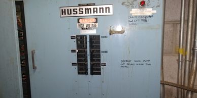
RDP Panel
On refrigeration systems with ELECTRIC defrost, the breakers, contactors, and heaters are on a separate electrical panel. This is done because of the large amp draw. It would be to much to be included in the REFRIGERATION electrical panel so it has to split apart.

High Moisture Drier
These are used when moisture is present inside a refrigeration system. These remove the moisture that causes acid to form, txv’s to freeze up, etc.
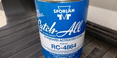
4864 Drier Core
These are used when moisture is present inside a refrigeration system. These remove the moisture that causes acid to form, txv’s to freeze up, etc.
EPR / ORIT
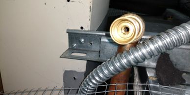
ORIT
This is the adjustment end used to adjust the pressure which controls the TEMPERATURE. To adjust this use an ALLEN wrench along with a temperature and pressure chart.
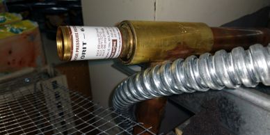
ORIT 2
Another picture of the ORIT. The pipe coming out of the body is the OUTLET and the other end is the INLET, or the EVAPORATOR side. The other side is the leaving side going BACK to the compressor/compressors.
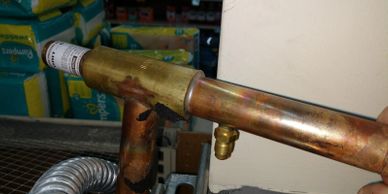
ORIT 3
Notice the schrader port to put your gauge on. By putting your gauges on here this is how you can adjust the pressure. The “T” at the end of the word ORIT means “TAP”. If it is a SORIT, the “S” denotes SOLENOID and the “T” of course means TAP. This is still considered an EPR but it is strictly mechanical. This can be found in the case, under the case, or on top of the case. They have been known to be installed on the rack on the suction header in the motor room.

SORIT (EPR) Inside of Case Lineup
As I have mentioned early on in the website this location is where an EPR can be located, usually for a single lineup. During the construction phase its easier to put the EPR inside the case VS on the suction side of a ONE-ON-ONE compressor system.
NOTE: S= SOLENOID
T= TAP for your gauges (SUCTION)
More Components

Wiring Diagram 8145-20 Time Clock
Basic wiring diagram for a time clock, now this one shows for hot gas defrost, next to never is a time clock used for hot gas, almost always used for electric defrost. There’s also a diagram on the inside cover of the time clocks as well.
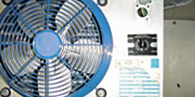
Fan Delay / Defrost Termination
This component is used in the defrost mode. After defrost it will delay the fans until the coil gets to 20 degrees. It terminates defrost once the coil hits 48 degrees.

Evaporator Condenser Tower
These type of condensers tend to be used in hotter climates, due in part that they can withstand the high ambient temperatures. They work by spraying water on a TUBING BUNDLE, and blowing air over them. It is like standing in front of a fan when your clothes are wet, creating the AIR CONDITIONING effect. NOTE: When leak checking a store, DO NOT FORGET to check this item. They have a high tendency for leaks. To leak check simply shut off the water pump, let the fan dry out the coils, remove the side covers nearest the SUMP, and put your leak detector inside.

Three Wire Klixon
This is a three wire klixon. It works as a defrost termination/fan delay. Fan delay is designed to keep the fans off until the coil reaches 20 degrees to freeze any remaining moisture on the coil after defrost, and any water that has not drained from the fins of the coil. NOTE: If the KLIXON goes bad, you can trace out the fan circuitry wiring and JUMP it out to get the fans going. Then come back and replace KLIXON.
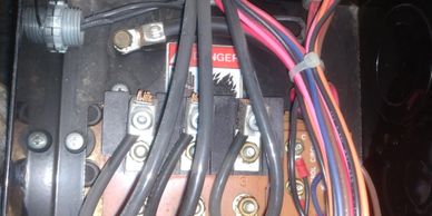
Wiring on Compressor
This is the wiring inside of a COPELAND compressor. The big wires are the 3PHASE electricity for the electric motor inside the compressor. Also there are the control terminals. They are labeled as follows: S1, S2, S3, S4, M1, and M2. The “S” terminals are sensors. They have been known to go bad. Usually the compressor will short cycle on/off in rapid succession. If this happens, you can put a 2500 OHM resistor in SERIES with the bad sensor. Use your OHM meter to find the bad sensor.

Floodback
This is a sign of floodback. Notice how the SUCTION line is frosted. In order to de-ice this, TURN OFF ALL POWER and use HOT water to de-ice this iceball. BE very careful not to make a mess inside the walk in.
Follow these steps on your journey to becoming a Journeyman!
