Items Associated with the Liquid Circuit
EVAPORATOR CONDENSER TOWER
LIQUID HOLD BACK VALVE


At the top of the tower, the copper water lines are known as DISCREET sprayers. In case the water pump goes out, the spray bars can still get water to them from city water pressure. They can be actuated one of two ways, either by a ball valve, or by a solenoid with a switch on the electrical panel.
This is what creates the differential in the main liquid line for hot gas defrost systems, so when the hot gas that goes to the cases comes back it will most generally come back in liquid form (condensed) Generally the differential is 25 PSI (Can be higher/lower) between the inlet and outlet of the valve. When no systems are in defrost, there is NO differential. The solenoid energizing creates the differential when a circuit goes into defrost.
HIGH & LOW SPEED MOTORS
AIR COOLED CONDENSER


On most towers there are low and high speed fan motors. Slow speed to keep condensing pressures/temperatures fairly consistent, and high speed when there is a heavy load on the refrigeration system i.e., like a really hot day, or a lineup just coming out of defrost.
Notice the receiver underneath the condenser. It is not uncommon to see this done where the condenser and receiver are in close proximity. This is widely done with HUSSMANN PROTOCOL systems.
THERMOSTATS
WATER PUMP FOR
CONDENSER TOWER


These thermostats can be used to control the condenser (EVAPORATIVE TYPE) in a few ways. Either by sump water temp, drop leg temp, or can be used as freeze stats as well. Meaning if the ambient temperature gets to LOW they can shut off the contactor( CONTROL) side to keep the condenser from stacking liquid, and/or to keep the water from freezing.
The water pump is to pump water from the tower sump up to the spray bars. These pumps do go bad i.e., shaft seals leak, motor burns up, etc. NOTE: If you have to install a new pump, rotation is very critical. Always check rotation. They tend to be 3 phase motors, so if you need to reverse the rotation, switch any 2 phases. That applies to ALL 3 phase motors.
EVAPORATOR CONDENSER TOWER
At the top of the tower, the copper water lines are known as DISCREET sprayers. In case the water pump goes out, the spray bars can still get water to them from city water pressure. They can be actuated one of two ways, either by a ball valve, or by a solenoid with a switch on the electrical panel.
LIQUID HOLD BACK VALVE
This is what creates the differential in the main liquid line for hot gas defrost systems so when the hot gas that goes to the cases comes back it will most generally come backin liquid for (condensed) Generally the differential is generally 25 PSI between the inlet and outlet of the valve. When no systems are in defrost, there is NO differential. The solenoid energizing creates the differential when a circuit goes into defrost.
HIGH & LOW SPEED MOTORS
On most towers there are low and high speed fan motors. Slow speed to keep condensing pressures/temperatures fairly consistent, and high speed when there is a heavy load on the refrigeration system i.e., like a really hot day, or a lineup just coming out of defrost.
AIR COOLED CONDENSER
Notice the receiver underneath the condenser. It is not uncommon to see this done where the condenser and receiver are in close proximity. This is widely done with HUSSMANN PROTOCOL systems.
THERMOSTATS
These thermostats can be used to control the condenser (EVAPORATIVE TYPE) in a few ways. Either by sump water temp, drop leg temp, or can be used as freeze stats as well. Meaning if the ambient temperature gets to LOW they can shut off the contactor( CONTROL) side to keep the condenser from stacking liquid, and/or to keep the water from freezing.
WATER PUMP FOR
CONDENSER TOWER
The water pump is to pump water from the tower sump up to the spray bars. These pumps do go bad i.e., shaft seals leak, motor burns up, etc. NOTE: If you have to install a new pump, rotation is very critical. Always check rotation. They tend to be 3 phase motors, so if you need to reverse the rotation, switch any 2 phases. That applies to ALL 3 phase motors.
Tube N Shell Condensers
TUBE N SHELL
TUBE N SHELL 2


How this works: The discharge line goes in the shell and the water flows through the tubes. The refrigerant and water flow in OPPOSITE directions for proper heat transfer to take place. NOTE:Tube N Shell condensers are sized according to the horsepower of the compressor/Compressors.
Also on a tube n shell condenser, if the water is not properly treated the copper tube bundle will form scale inside them, causing HIGH discharge pressures. In that case you have to pump down the system, remove the end bell OPPOSITE of where the water inlet and outlet is and ROD them out. Meaning using a long skinny brush attatched to the end of a cordless drill to clean out the the passes.
EPR & LLS WIRED TOGETHER
OLD STYLE EPR


What you see here is an EPR & LLS wired to work together, so when the EPR is shutoff for defrost, power loss the power will also be shutoff to the LLS, now there are numerous reasons this is done:
1) If the store loses power all the refrigerant will not migrate down stairs to the cases.
2) In a defrost situation the refrigerant will be locked in place so when system does come out of defrost the compressor (ONE ON ONE) system will not get overloaded upon start up.
What you see here is an old style EPR, works the same as any other EPR.
On the bottom you see a big canister looking object, this is where the adjustment screw is. You use your service wrench and gauges to adjust accordingly.
The top valve is for shutting off the circuit, meaning to isolate circuit at the rack.
PUMPING DOWN A CIRCUIT
BALL VALVES WITH
SCHRADER PORTS


What see here is the fastest way to pump down a single circuit. First shutoff the liquid line ball valve, then hookup your gauges to the liquid line and to the suction line then open the valve on your gauge port so that it goes to the center hose and into the suction line, you will pump down a circuit much quicker doing this step.
Notice how the ball valve (Liquid) installed here have schrader ports pointing towards the EVAPORATOR, now this is very important, as this will help aid in pumping down the coil, ALWAYS be aware of which direction the schrader ports are pointing, because if they are pointed in the wrong direction then you will have to pump down the entire circuit which in turn will equate to much wasted time. ( Notice how the red hose is on the liquid port) that is to pump out the liquid into the suction line.
TUBE N SHELL
How this works: The discharge line goes in the shell and the water flows through the tubes. The refrigerant and water flow in OPPOSITE directions for proper heat transfer to take place. NOTE:Tube N Shell condensers are sized according to the horsepower of the compressor/Compressors.
TUBE N SHELL 2
Also on a tube n shell condenser, if the water is not properly treated the copper tube bundle will form scale inside them, causing HIGH discharge pressures. In that case you have to pump down the system, remove the end bell OPPOSITE of where the water inlet and outlet is and ROD them out. Meaning using a long skinny brush attatched to the end of a cordless drill to clean out the the passes.
EPR & LLS WIRED TOGETHER
What you see here is an EPR & LLS wired to work together, so when the EPR is shutoff for defrost, power loss the power will also be shutoff to the LLS, now there are numerous reasons this is done:
1) If the store loses power all the refrigerant will not migrate down stairs to the cases.
2) In a defrost situation the refrigerant will be locked in place so when system does come out of defrost the compressor (ONE ON ONE) system will not get overloaded upon start up.
OLD STYLE EPR
What you see here is an old style EPR, works the same as any other EPR.
On the bottom you see a big canister looking object, this is where the adjustment screw is. You use your service wrench and gauges to adjust accordingly.
The top valve is for shutting off the circuit, meaning to isolate circuit at the rack.
PUMPING DOWN A CIRCUIT
What see here is the fastest way to pump down a single circuit. First shutoff the liquid line ball valve, then hookup your gauges to the liquid line and to the suction line then open the valve on your gauge port so that it goes to the center hose and into the suction line, you will pump down a circuit much quicker doing this step.
BALL VALVES WITH
SCHRADER PORTS
Notice how the ball valve (Liquid) installed here have schrader ports pointing towards the EVAPORATOR, now this is very important, as this will help aid in pumping down the coil, ALWAYS be aware of which direction the schrader ports are pointing, because if they are pointed in the wrong direction then you will have to pump down the entire circuit which in turn will equate to much wasted time. ( Notice how the red hose is on the liquid port) that is to pump out the liquid into the suction line.
Various Liquid Components
4864 DRIER
RECEIVER


This is a liquid drier/filter attached to a rack. It houses 4864 drier cores. There are three types of driers:
HH=High Acid drier, for compressor burnouts
RCW 48=For high moisture content inside system
4864= Regular driers for debris, to keep the system clean overall.
Notice the little sight glasses on this vertical reciever, it indicates what kind of liquid level you have.
LIQUID BALL VALVE
LIQUID SUB COOLER


This is a liquid ball valve used to isolate or shutoff the liquid to a particular lineup/case. Used to “PUMP DOWN” a case.
A liquid subcooler is used to cool the liquid BEFORE it goes out to the cases. It is a refrigeration system unto itself and generally cools the liquid from approx 90-95 degrees to somewhere near 50 degrees, depending on the set point. This is done to prevent “FLASHGAS” from the TXV OUTLET and can pickup more BTU’s. Also the case manufacturer can slightly undersize an evaporator coil by having SUBCOOLED liquid going to it.
LIQUID INLET
PLUGGED 4864 DRIER CORE


This is where the Liquid refrigerant enters the 4864 drier shell before it goes out to the cases.
Notice how this drier core has copious amounts of debris on it, this will cause refrigeration issues ultimately at the cases in the form of constant temperature issues due to lack of liquid getting to TXVs.
LIQUID HAND VALVE
MANUEL STEM LLS


This is a liquid hand valve and is generally located inside the case itself. On rare occasions you will see them inside motor rooms, on the individual liquid line circuit.
This is a Liquid line solenoid. Notice how it has a manual stem like the EPR. If needed you can turn in the stem for manual operation in an emergency. When you are done, make sure to turn the stem back OUT. NOTE: If you have a case/box coil flooding, or iced up, it is a good idea to check and make sure the stem is OUT. There have been numerous times when somebody forgets to do so, and left the stem turned in. Same thing applies on an EPR.
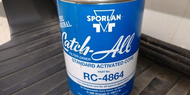
FILTER DRIER
HIGH MOISTURE DRIER
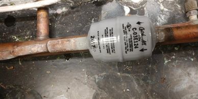

Notice how this drier is frosted up on the OUTLET side. This is a classic example of a plugged drier. This is usually associated with a service call of “case running warm”. In this case you will have to pump down the case to 0 PSI, cut this drier out, weld in a straight piece of copper pipe, braze it, use a vacuum pump to get the air out of the system, and then start it back up. Sometimes it is helpful to put on the vacuum pump ahead of time. Once the system is at 0 PSI, this helps to get any and all residual refrigerant vapor from the lines, and makes it easier to braze without getting phosgene gassed. NOTE: If there is NO schrader/gauge port on the liquid line, PUT ONE IN to make the job easier for the next service tech. You can also use the suction schrader/gauge port. The system is intertwined, meaning it is a closed loop. The vacuum pump will remove the air from the suction and liquid side because they are still connected together.
These are used when moisture is present inside a refrigeration system. These remove the moisture that causes acid to form, txv’s to freeze up, etc.Notice how this drier core has copious amounts of debris on it, this will cause refrigeration issues ultimately at the cases in the form of constant temperature issues due to lack of liquid getting to TXVs.
LIQUID LINE STABILZER
4864 DRIER CORE

Very rarely will you see these but just should mention alittle about it..Basically how it works is liquid would come in to it and it would pool on the bottom of this so as to keep a solid stream of liquid at all times to the TXV . Its not really a heat exchanger. Was predominantly used with R22 systems on old Albertsons stores because they would float the head pressure very low, so the thinking was this would stabilize the liquid in the cases.
This is the most common used drier in grocery store refrigeration systems. They simply filter out various debris and some moisture.
LIQUID DRIER
SUCTION LINE ACCUMULATOR


Cut away view of a flare fitting drier..On these types of driers if the is an “S” on the end means sweat (Brazed) and if there is an “F” it means flare fitting.
What you see here is a suction line accumulator, the reason an accumulator is used is to prevent liquid refrigerant from hitting the compressor/compressors in the unlikely event of a floodback situation, it will hold the liquid until it is boiled off inside to become a vapor to go the compressors, also inside of it at the bottom is a weep hole so oil may return to the compressor as well
4864 DRIER
This is a liquid drier/filter attached to a rack. It houses 4864 drier cores. There are three types of driers:
HH=High Acid drier, for compressor burnouts
RCW 48=For high moisture content inside system
4864= Regular driers for debris, to keep the system clean overall.
RECEIVER
Notice the little sight glasses on this vertical reciever, it indicates what kind of liquid level you have.
LIQUID BALL VALVE
This is a liquid ball valve used to isolate or shutoff the liquid to a particular lineup/case. Used to “PUMP DOWN” a case.
LIQUID SUB COOLER
A liquid subcooler is used to cool the liquid BEFORE it goes out to the cases. It is a refrigeration system unto itself and generally cools the liquid from approx 90-95 degrees to somewhere near 50 degrees, depending on the set point. This is done to prevent “FLASHGAS” from the TXV OUTLET and can pickup more BTU’s. Also the case manufacturer can slightly undersize an evaporator coil by having SUBCOOLED liquid going to it.
LIQUID INLET
This is where the Liquid refrigerant enters the 4864 drier shell before it goes out to the cases.
PLUGGED 4864 DRIER CORE
Notice how this drier core has copious amounts of debris on it, this will cause refrigeration issues ultimately at the cases in the form of constant temperature issues due to lack of liquid getting to TXVs.
About Liquid Refrigeration
What happens is after the refrigerant vapor goes through the condenser and is condensed to liquid, it generally goes to the receiver, through the drier cores out to the sales floor to the various cases, through the TXV’s out the suction line, and back to the compressors to start the cycle all over again. In the above pictures I have various components you will deal with in grocery stores. Let’s go through the various items here. One is a sub cooler. The purpose of a sub cooler is to cool the refrigerant going out to the sales floor to the various cases. This is so the manufacturers of the cases can use smaller evaporator coils. Also sub cooled liquid will prevent “FLASH GAS” from coming OUT of the TXV outlet. Therefore it (REFRIGERANT), can pickup MORE BTU’s with colder liquid as opposed to liquid entering in at approximately 90 degrees. The subcooled liquid generally enters the evaporator at approximately 50 degrees, maybe higher or lower depending on stores/Manufacture specs. The receiver is what receives the liquid refrigerant and holds it in reserve for when the cases on the sales floor need more liquid.Once the liquid refrigerant leaves the receiver, it goes through the 4864 drier cores to remove any debris within the liquid refrigerant. From there it goes to the liquid MANIFOLD or HEADER, then to the cases out in the store. If the need arises to add refrigerant to the system and there is no indication of how much the the system holds you can use the following formula:
15 LBS of refrigerant per horsepower of compressors
(Example) 15 times 30 equals 450 and so forth..NOTE: Some compressors may NOT have horsepower rating info but instead use BTU rating use the formula of 2545 BTUs per horsepower as well.
Troubleshooting the Liquid Circuit
In this section we will talk about what and how to check for issues related to the liquid, if you suspect problems, such as cases starving for liquid, cases not holding temperature, etc. As has been mentioned in the above section, start by verifying the condenser is running properly. Let’s start with the receiver. Most receivers have a “SIGHT GLASS” to see the liquid level. What is the level? There will be a sight glass on the liquid header, is it solid? You want a solid sight glass. If it is “FLASHING”, RIVERING, or NO liquid at all, then put your gauges on the INLET and OUTLET of the 4864 drier core shell. If there is a pressure differential, then you probably have PLUGGED drier cores. Before you do this MAKE SURE the receiver has a proper level of liquid in it. If no liquid is present in the receiver sight glass, the probability exists that the system is low on liquid, which means there is a LEAK somewhere. At this time you will need to add liquid. If the rack is not marked with the type of refrigerant it uses, you can always check the TXV’s on the sales floor, or call in to the supply house with compressor model and serial number. 99% of the time its “RACK” is marked. Getting back to the drier cores, if there is a good level in the receiver and there is a pressure differential on the 4864 drier cores, then change them, by shutting off the “INLET” to the drier shell. NOTE: The liquid enters the shell by the lid or cap of the shell, where the bolts hold it on. After you turn off the valve you may have to wait for awhile, to get ALL the liquid out of the header and into the receiver. After that shutoff the ball valve to the OUTLET of the 4864 shell. BEFORE you loosen the bolts, make ABSOLUTE sure your gauges read “0” psi or you will get hurt. Be careful when doing this step. NOTE: After installing new drier cores it is important to evacuate the drier shell afterwards to remove any ambient air/moisture.
Follow these steps on your journey to becoming a Journeyman!