Refrigeration Compressors
COPELAND MEDIUM TEMP
COMPRESSOR
COPELAND LOW TEMP COMPRESSOR


This is a MEDIUM temp compressor on a MEDIUM temp rack. A medium temp rack can run in temperature range from +16 to +21. Cases generally associated in this range will be Multi Deck meat, Deli, Dairy walk in as examples.
The fan on top of the compressor always means LOW TEMP, due to compression ratios, and extra heat generated. NOTE: NOT directional sensitive (COMPRESSOR) it can spin in either direction.
CARLYSLE DIRECT DRIVE 5H80
COPELAND COMPRESSOR

This is a CARLYSLE 5H80, the “80” means “8” cylinders. The number at the end means number of cylinders 40=4 cylinders, etc. NOTE: These particular compressors are ROTATION sensitive meaning they can ONLY spin in ONE direction.Directional sensitive do to the oil pump must spin/turn in ONE direction ONLY.
https://www.carlylecompressor.com/carlyle/en/worldwide/products/compressor/5h/
This a 6 cylinder Copeland compressor with unloaders. The solenoids will DE-energize when refrigeration is needed, or ENERGIZE when NO refrigeration is needed. Saves electricity from constantly shutting on/off.
BITZER LOW TEMP COMPRESSOR
COPELAND SCROLL COMPRESSOR


The BITZER compressor has some of the same features that a COPELAND has, these however are German made compressors.
This is a scroll compressor which is very common to use in HUSSMANN PROTOCOL racks, and one-on-one systems. NOTE: DIRECTION sensitive must only spin in ONE direction. The way to find out if it is hooked up (ELECTRICALLY) correct is when you start it up and the discharge is COLD, and the SUCTION line is hot. Then reverse any two phase leads.
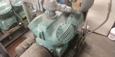
CARLYSE TWO STAGE COMPRESSOR
CARLYSLE COMPOUND COMPRESSOR DIAGRAM
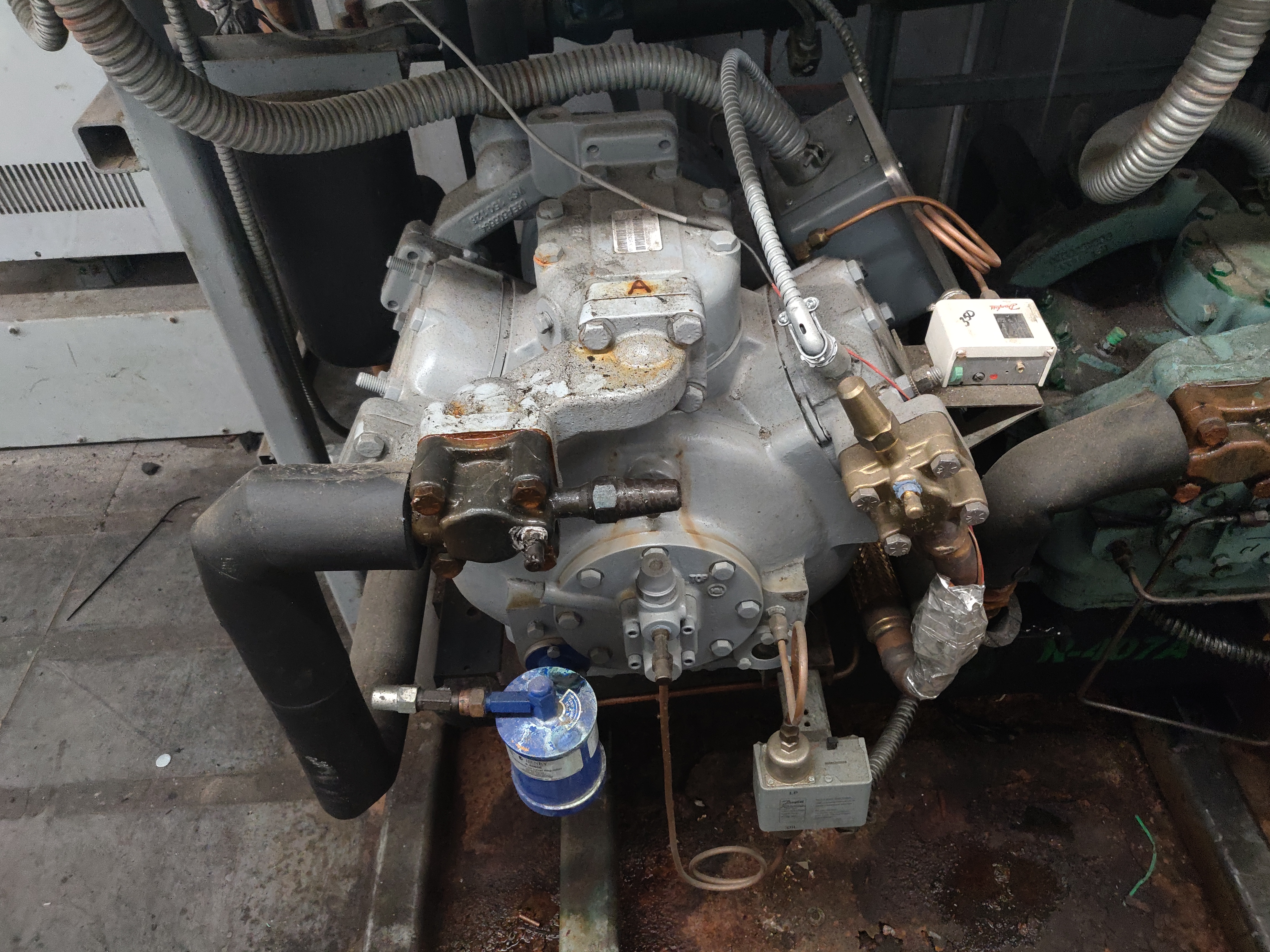

What you see here is a two stage carlyse compressor, mostly used on R22 low temp systems. The reason for two stage is to bring down the head/discharge pressure thus bringing down the temperature, R22 used in low temp aplications has a tendency to beat up the oil, thus causing oil flow issues.
What you see here is a pictorial diagram of how the Carlysle two stage or Compound cooling compressor looks like.
https://www.utcccs-cdn.com/hvac/docs/2002/Public/0B/574-066.pdf
COPELAND PARTIAL START WINDING CONTACTORS.
INSIDE WIRING COPELAND COMPRESSOR.


What your seeing here is two contactors for a COPELAND partial start winding compressor..How this works is because this compressor requires a lot of LRA and to prevent that from happening is the Manufacturer uses two sets of windings to breakup the high current inrush by staging the contactors approximately 1.5 to 3 seconds apart, meaning one contactor will engage then a few seconds later the second contactor will pull in, this is done via a TDR or time delay relay.
This picture shows how the compressor wiring inside the electrical box of the compressor. Notice there are six wires. Three wires per start winding.
COPELAND MEDIUM TEMP
COMPRESSOR
This is a MEDIUM temp compressor on a MEDIUM temp rack. A medium temp rack can run in temperature range from +16 to +21. Cases generally associated in this range will be Multi Deck meat, Deli, Dairy walk in as examples.
COPELAND LOW TEMP COMPRESSOR
The fan on top of the compressor always means LOW TEMP, due to compression ratios, and extra heat generated. NOTE: NOT directional sensitive (COMPRESSOR) it can spin in either direction.
CARLYSLE DIRECT DRIVE 5H80
This is a CARLYSLE 5H80, the “80” means “8” cylinders. The number at the end means number of cylinders 40=4 cylinders, etc. NOTE: These particular compressors are ROTATION sensitive meaning they can ONLY spin in ONE direction.Directional sensitive do to the oil pump must spin/turn in ONE direction ONLY.
https://www.carlylecompressor.com/carlyle/en/worldwide/products/compressor/5h/
COPELAND COMPRESSOR
This a 6 cylinder Copeland compressor with unloaders. The solenoids will DE-energize when refrigeration is needed, or ENERGIZE when NO refrigeration is needed. Saves electricity from constantly shutting on/off.
BITZER LOW TEMP COMPRESSOR
The BITZER compressor has some of the same features that a COPELAND has, these however are German made compressors.
COPELAND SCROLL COMPRESSOR
This is a scroll compressor which is very common to use in HUSSMANN PROTOCOL racks, and one-on-one systems. NOTE: DIRECTION sensitive must only spin in ONE direction. The way to find out if it is hooked up (ELECTRICALLY) correct is when you start it up and the discharge is COLD, and the SUCTION line is hot. Then reverse any two phase leads.
CARLYSE TWO STAGE COMPRESSOR
What you see here is a two stage carlyse compressor, mostly used on R22 low temp systems
CARLYSLE COMPOUND COMPRESSOR DIAGRAM
What you see here is a pictorial diagram of how the Carlysle two stage or Compound cooling compressor looks like.
https://www.utcccs-cdn.com/hvac/docs/2002/Public/0B/574-066.pdf
General Information About Compressors

This is a Copeland six cylinder compressor. The solenoids pictured on the compressor are called “Unloaders.” They are used to keep the compressor running. They are much more energy efficient versus having the compressor turn on and off, causing high energy usage. The compressor will load and unload according to the refrigeration or cooling capacity needed by the cases on the sales floor. If everything on the sales floor is at setpoint, then the compressor will unload and “ENERGIZE” the solenoid. When the compressor is needed for more refrigeration capacity the solenoid will “DE-ENERGIZE” starting the refrigeration cycle.
How Compressors Work?
Compressors do two things: It (Compressor) creates a pressure differential to move refrigerant around to cool products/remove heat and compresses the refrigerant to HIGHER than the saturation point of the gas, to aid in proper condensing of the gas to a liquid. Pressure does not change, it merely changes state, from a hot gas to a subcooled liquid.
Troubleshooting Compressors
Electrical Problems
There are three things that can go wrong with compressors. They can be “SCRAMBLED”, “OPEN WINDINGS”, or “SHORTED TO GROUND.” What follows are instructions on how to troubleshoot a compressor.
First turn OFF the control toggle switch, then turn OFF the BREAKER. Use your meter to make ABSOLUTELY sure there is NO VOLTAGE, then proceed to the next step.
Take your meter and measure the ohmic value on the “LOAD” side of the compressor. Measure all three legs L-1 to L-2, L-1 to L-3, L-2 to L-3, then measure each leg to a ground source. Of course make sure the breaker is “OFF.” If you get an ohmic reading to GROUND on any one of the load side, afterwords go to the electrical box on the compressor and remove the wires from the lugs and ohm windings again if readings are the same then you have a “Grounded” compressor. If any one of the legs on the compressor read “infinity” or NO ohm value then you have an “OPEN” winding on the compressor. The above is for 3 phase compressors. On a single phase compressor, like a self contained unit with the power turned “OFF,” pull the wires from the terminals. Between CSR= COMMON START RUN you should have an ohmic value, the measure to a ground. If you get a reading the compressor is once again “GROUNDED.” If no ohmic value is read between CSR then the compressor is “OPEN.” All of the above scenarios require the compressor to be replaced! One more thing to check, is to clamp your amp probe around the C wire on a single phase compressor. If you get a HIGH amp draw, and the compressor DOES NOT start up, then the compressor is LOCKED up,or has bad start components. On a rack compressor if you suspect a problem, once again clamp your amp probe around one of the three phases. If you have a HIGH amp draw and the END bell is hot, this a sign that the windings are bad on the compressor. NOTE: These types of compressors are called RECIPROCAL compressors. There are many types of compressors: screw, rotary vane, and scroll. The three most common types used in grocery store refrigeration are RECIPROCAL, SCREW and SCROLL. Reciprocal like the ones pictured on this site, ARE not rotation sensitive. Most open drive compressors ARE rotation sensitive, meaning they can only spin in ONE direction. This is because the oil pump must only go ONE direction. SCREW compressors and SCROLL compressors ARE rotation sensitive! But the Copeland compressors used widely in grocery stores can go in either direction. Sometimes you can reverse the rotation if you are having problems with oil failures.
Mechanical Problems
Now you have some basics on the “ELECTRICAL” troubleshooting, let’s talk about the mechanical end of things. First, always put your gauges on the compressor you suspect. If you have HIGH suction, LOW discharge that indicates bad valves. Feel the back of the compressor, the end bell. If it is HOT that is another indicator of bad valves.To check for bad valves on a compressor out your gauges on the suction port of the compressor,front seat or close off the suction service valve,when compressor pumps down it should to 0 psi on your gauges,if f your gauges start to climb pressure wise, then you have bad valves, if your gauges stay at 0 psi then the valves are good.NOTE: before pumping down compressor shut off the oil line to the compressor. Next check the oil pressure. To find this subtract the SUCTION from STATIC oil pressure. This equals NOP (Net Oil Pressure). If you have low oil presure check to make sure there is oil in the compressor. On a COPELAND it should be 1/2 to 3/4 full sight glass. On a CARLYLE, oil needs 1/3 full sight glass. NOTE: Carlyle runs a LOWER NOP than a COPELAND compressor. If low oil pressure is detected, pump compressor down by FRONT SEATING suction service valve on compressor. Let it get to 3-5 PSI then turn control switch and breaker OFF. CLOSE discharge service valve, bleed compressor to 0 psi, and drain oil. On Copeland you need either a 1/2″ wrench or 1 7/16″ big socket to remove the block. With your finger reach in and remove oil screen and spray it clean. Use electrical contact cleaner until you see light thru it, then put back in. Put bolts/bolt in and pump in one gallon of oil. Depending on refrigerant it will need either POE,Mineral oil or Alka Benzene. Then close gauge handles and open DISCHARGE FIRST. Slowly open back suction service valve and recheck NOP. All should be good but not always. One last things to check is AMP draw. There will be a NOMANCLATURE plate on the compressor. You should be fairly close to amp draw on plate versus actual amp draw.
Another subject is oil problems inside the compressor, if you notice the compressor pumps out the oil or always seems to be low on oil level, something to check is the sump pressure if it is abnormally high and the sump is very hot you may have a situation where the piston rings are worn out and the hot gas (discharge) is bypassing the rings what will happen is the pressure will cause the check valve to CLOSE and pump out the oil, now to check this shut the compressor off and let the pressures come down and if the sump fills up with oil then you have an OIL PUMPER, because what happens as the sump pressure comes down the check valve will OPEN and let oil in from the suction side end bell that has been being held back by the high sump pressure thus keeping the check valve inside CLOSE.
NOTE: COPELAND specs say the discharge should never be any higher than 225 degrees and the end bell should never be higher than 60 degrees.
Various Scenarios You May Find
PICKUP SCREEN
SCRAMBLED COMPRESSOR


This dirty screen will cause Low oil pressure and compressor to trip off on “OIL FAILURE”.
If you have a compressor that looks like this inside of it, you will usually see low or no oil pressure, low amp draw, a terrible knocking sound coming from compressor, or high suction.
BROKEN VALVES

This dirty screen will cause Low oil pressure and compressor to trip off on “OIL FAILURE”.
PICKUP SCREEN
This dirty screen will cause Low oil pressure and compressor to trip off on “OIL FAILURE”.
SCRAMBLED COMPRESSOR
If you have a compressor that looks like this inside of it, you will usually see low or no oil pressure, low amp draw, a terrible knocking sound coming from compressor, or high suction.
BROKEN VALVES
This dirty screen will cause Low oil pressure and compressor to trip off on “OIL FAILURE”.
Other Compressor Parts You Should Know
COMPRESSOR OIL SIGHT GLASS
SENTRONIC OIL PRESSURE
TRANSDUCER


Through this glass is where you can see your oil level of how much oil is inside the compressor. NOTE: On a copeland you want to see approximately 3/4 full on the sight glass. On a Carlyse compressor you only need approximately 2/3 full of oil inside your sight glass. Also when doing an oil change on a compressor take the extra 10 minutes to clean the sight glass, to remove the bolts use a 7/16″ socket or wrench.
This is an oil pressure sensing transducer. Always clean this item whenever you are changing oil in a compressor. NOTE: This is only specific to a copeland compressor, and take note of the rubber “O” ring towards the end of the transducer, make absolutely sure it is on, otherwise you will get an oil failure alarm, the reason is the oil will BYPASS going through the center orifice and go directly through the screen, thus NOT sensing oil pressure even though there is actual oil pressure.
DEMAND COOLING SENSOR
DISCHARGE MUFFLER

What you see here is a demand cooling sensor. Demand cooling is ONLY used on R22 LOW TEMP COMPRESSORS. Briefly how this works it senses head Temperature, and based on resistance it will signal the demand cooling module to OPEN up the liquid injection valve to aid in the cooling of the compressor due to high compression ratios.
A discharge muffler is used to smooth out the pulsations of the compressor, much like a muffler on a car, with the pistons moving up and down. Without it your gauge needle would bounce back and forth.
SUCTION FILTER
SUCTION FILTER 2


What you see here is a suction cannister filter, now generally these are removed after startup but not always, these are installed to catch any debris from construction inside the suction linesm however if they are left in they tend to get plugged up if you are having problems with the rack not making suction pressure, put your gauges on the cannister and the back of the compressor suction port, if there is a differential then most likely these are plugged, in that case simply removed, clean the inside of the cannister and bolt the lid back on.
Same picture just a different angle, notice the debris in it, such as copper shavings, copper pipe soot from brazing.
SUCTION FILTER INSIDE VIEW
COMPRESSOR DECK


Inside view of a suction filter, as you can see there is some debris inside, but over all not too bad.
When having to replace either the gaskets/valve plate start by scraping the old gasket material off, and there are numerous ways this can be done.A 1.5″ wide wood chisel scraper and WD40 works wonders Take note of the front and rear roll pins that are sticking up from the deck, do not lose those or misplace, they are very important to have as they will help align the valve plate & head for final assembly.
VALVE PLATE INSTALLED
6D COMPRESSOR HEAD


After the first gasket is installed on the compressor deck, next istall the valve plate and the final gasket. NOTE: It is fine to oil the gaskets liberally to help get a better seal when doing the final assembly .
This is the final assembly of the valve plate and head with gaskest. NOTE: The small diamond shape looking plate to the rear left is for an unloader, meaning this compressor can be setup to run with an unloader, but on this particular compressor the option was not used. NOTE: Do not forget there is a small gasket under the unloader plate that needs to be replaced as well. Final phase when tighting the bolts do so in a “STAR” pattern,meaning front right, left rear and criss cross, DO NOT tightened the bolts down on the first go around, tighten them just barely snug and as you make your way around tighten incrementally, after they are ALL fairly tight then go around the head and give them the final tightning, it is recommended that you use a torque wrench and tighten to manufacturer specs.
COMPRESSOR OIL SIGHT GLASS
Through this glass is where you can see your oil level of how much oil is inside the compressor. NOTE: On a copeland you want to see approximately 3/4 full on the sight glass. On a Carlyse compressor you only need approximately 2/3 full of oil inside your sight glass. Also when doing an oil change on a compressor take the extra 10 minutes to clean the sight glass, to remove the bolts use a 7/16″ socket or wrench.
SENTRONIC OIL PRESSURE
TRANSDUCER
This is an oil pressure sensing transducer. Always clean this item whenever you are changing oil in a compressor. NOTE: This is only specific to a copeland compressor, and take note of the rubber “O” ring towards the end of the transducer, make absolutely sure it is on, otherwise you will get an oil failure alarm, the reason is the oil will BYPASS going through the center orifice and go directly through the screen, thus NOT sensing oil pressure even though there is actual oil pressure.
DEMAND COOLING SENSOR
What you see here is a demand cooling sensor. Demand cooling is ONLY used on R22 LOW TEMP COMPRESSORS. Briefly how this works it senses head Temperature, and based on resistance it will signal the demand cooling module to OPEN up the liquid injection valve to aid in the cooling of the compressor due to high compression ratios.
Follow these steps on your journey to becoming a Journeyman!